|
|
||
|
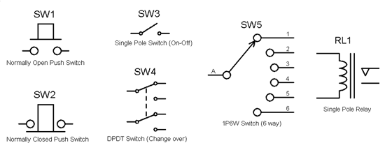
Switches & Relays Switches and relays provide a means of connecting and disconnecting power and signals to an electric circuit. A switch is operated by a lever or button and must be operated either manually or by some piece of mechanics, such as a limit stop in a machine control. A relay is simply a switch where the operating lever has been replaced by an electro-magnet. Circuit Symbols
All switches and relays have contact ratings that must be observed. These specify the maximum (and sometimes minimum) operating voltage and current that the switch can handle. Some contacts have more than one set of ratings that specify the acceptable limits under differing operating conditions. A relay has an additional rating for the coil that sets out the range of voltages than will give reliable operation. Some relay coils are specially designed to be driven by an AC source at low frequency (typically 50 - 60 Hz). When a switch or relay has multiple sets of contacts they are represented on a circuit diagram either by joining the contacts with a dotted line (as shown for SW4 in the above diagram) or by labelling each set of contacts with a differing suffix (SW6:A, SW6:B). There are a number of ways of describing the arrangement of contacts within any given switch or relay. Generally each individual set of contacts is referred to as a pole (which also means the common contact, or wiper in the set). Each pole can connect to a number of different positions referred to as ways or throws. Common terms are as follows:
|
||||||||||||||||||||||||||||||||||||||||||||
|
||||||||||||||||||||||||||||||||||||||||||||
|
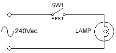
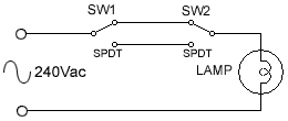
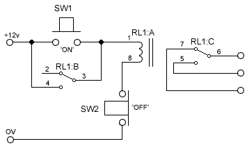
Sample Circuits
|
Safety Note |
When wiring a change over contact as a normally open or a normally closed contact always connect the incoming signal or power to the selected way and the out going signal or load to the common contact. This prevents the unused contact position from becoming live when the circuit is switched off. |


