|
|
||
|
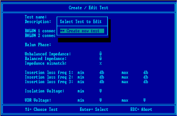
In Use The first task that must be completed is the creation of a suitable
test. A test is created, and may subsequently be edited, by selecting
the relevant option from the main menu. Each test is given an identifying
name and is saved for future use. It is possible to test either a
single balun or two identical baluns during a test.
The baluns matching impedances that fitted in the test set (and are easily interchanged) are specified in the edit screen. The allowable tolerance (or mismatch) for these and the baluns phase are also specified. These allow the initial tests to establish that the transformer is of the correct type and is connected correctly to the input and output connectors. Subsequent tests check the actual insertion loss, a measure of signal degradation, at key frequencies. These tests further ensure that the correct transformer core has been used in the assembly and that it is performing satisfactorily. Two final tests performed at an elevated voltage prove that the input and output have sufficient isolation from each other and that any voltage suppression devices fitted to the unbalanced signal lines are working correctly. Once a test has been set up the ‘Test BALUNs’ option is selected from the main menu. The operator is prompted to choose a predefined test from a list. They then enter their name, a batch identifying code and any salient comments about the batch test to be performed. Once this information has been entered the testing can proceed.
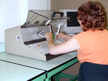
The actual testing is quite simple. The safety door is opened and a balun
to be tested is inserted into the fixed connector on the vertical panel.
Cables are attached to the exposed BNC connectors and the door closed.
During the course of the testing a tally is recorded of the number of devices that passed and failed. In addition the stage of the test at which each balun failed is recorded so that any statistical anomalies or batch process faults can be tracked and rectified. These results can be printed or exported for further processing and analysis. |
 |  |


 The operator can set up the parameters for a particular balun type
to ensure compliance with the specification and allow for production
tolerances.
 The test starts automatically as soon as the door is closed.
On the successful completion of all the tests, which only take a few
seconds, a buzzer sounds briefly to alert the operator and a green
‘PASS’ indicator lights to confirm success. If any test
fails the remaining tests are aborted and a red ‘FAIL’ indicator
lights. The operator can now remove the balun from the test equipment
and load it with the next piece to be tested.